
1. Introduction (Background & Objectives)
Outdoor lighting for urban roads and industrial parks often faces alternating extreme cold and heat (this paper uses −25°C to +45°C as a reference). To ensure LED streetlights achieve long-term stable operation (maintainable lumen maintenance, low failure rate, predictable lifetime) in this temperature range, the design must simultaneously address: LED thermal management, driver and electronic component reliability, sealing and anti-condensation measures, material weatherability and corrosion protection, electromagnetic and surge protection, and on-site maintenance strategies.
The following sections expand on each topic following a Cause–Solution–Verification structure to facilitate engineering implementation and procurement evaluation.
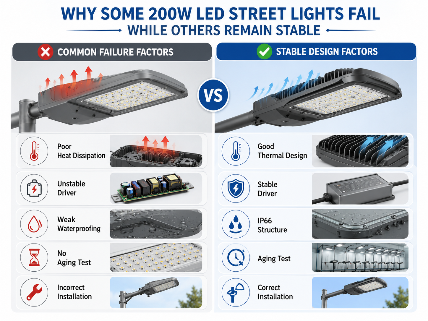
2. Why Temperature Range Matters (Key Failure Mechanisms)
LED Chip and Lumen Depreciation:
LED luminous efficiency and lifetime are strongly dependent on junction temperature (Tj) and case temperature (Tc). Elevated junction temperatures accelerate lumen depreciation and color shift. LM-80 and TM-21 are the industry-standard methods for measuring and projecting lumen maintenance, forming the basis for product lifetime and maintenance factor specifications.
Driver and Electronic Component Failures:
The driver’s electrolytic capacitors, switching devices, and ICs are highly temperature-sensitive. Electrolytic capacitor lifetime typically halves for every 10°C temperature rise (Arrhenius effect). Proper derating and component selection are critical to mitigate high-temperature degradation.
(Source: XP Power)
Sealing and Condensation:
Daily temperature swings, humidity, and pressure variations cause condensation inside sealed housings, leading to corrosion, short circuits, and optical contamination. Proper sealing and pressure equalization/anti-condensation systems are essential.
(Source: Gore)
Surge and Electromagnetic Disturbances:
Outdoor power networks are exposed to lightning and switching surges. Without adequate surge protection (tested to IEC 61000-4-5), drivers and control boards are vulnerable to damage.
(Source: EMC FastPass)
3. Design Guidelines (Practical Recommendations from Components to System Level)
Thermal Design (Heat Dissipation & Derating)
-
Minimize Thermal Resistance: Ensure efficient heat transfer from LED chip → PCB → thermal pad/compound → heatsink (die-cast aluminum or finned design) → ambient air. Maintain Tc below the manufacturer’s specified maximum.
-
Thermal Simulation (CFD): Verify steady-state Tj under +45°C ambient, accounting for solar load, windless conditions, and luminaire array effects.
-
Derating Operation: Follow manufacturer-provided derating curves to reduce drive current at elevated Ta, thereby extending lifetime and reducing lumen depreciation.
Driver & Electronic Component Selection
-
Wide Operating Temperature Range: Drivers should cover at least −40°C to +85°C, with guaranteed cold-start capability at −25°C.
-
High-Reliability Capacitors: Prefer solid/polymer capacitors or 105°C-rated electrolytics, with lifetime curves provided. Require documented lifetime calculations at specified ambient temperatures.
-
Protection & Performance: Drivers must include over-temperature protection, automatic derating, short/open-circuit protection, high power factor (PFC), and low THD.
Sealing, Venting & Anti-Condensation
-
Ingress Protection: Minimum IP65/66 per IEC 60529, with housing design incorporating breathable vents (e.g., GORE® vents) or valves to equalize pressure while blocking water, preventing condensation buildup.
-
Surface Treatment: For high humidity or coastal environments, use anodizing + polyester powder coating, stainless fasteners, and optionally desiccant packs for maintenance.
-
Design for Drainage: Avoid water-trapping features, use sealed threads or snap-in optics.
Materials & Optics
-
Housing: Use high thermal-conductivity aluminum alloys (ADC12 or A356), with anodized or powder-coated finish for corrosion resistance.
-
Lens/Window: Choose UV-stabilized PC with anti-yellowing formulation or tempered glass for stable long-term transmittance.
-
Seals: Use silicone or fluororubber gaskets rated for −40°C flexibility and ozone/chemical resistance.
Lightning & Surge Protection
-
SPD Installation: Provide space for surge protection device (SPD) at input; specify SPD class per IEC 61000-4-5 test level, including discharge capacity and residual voltage rating.
-
Driver Immunity: Drivers must integrate over-voltage suppression, CM/DM filtering, and meet IEC 61547/EN 55015 EMC compliance.
Controls, Communication & Low-Temperature Start-Up
-
Control Modules: DALI/PLC/wireless control modules and antennas must operate over the same temperature range as the luminaire.
-
Cold-Start Verification: Drivers must reliably start at −25°C; use soft-start control and current-limiting circuits to ensure startup under cold-load conditions.
4. Verification & Testing (To Be Specified in Acceptance Criteria)
To guarantee operability between −25°C and +45°C, require the following tests and original reports:
-
LM-80 Data & TM-21 Projections: To validate lumen maintenance and predict lifetime.
-
IP & Condensation Testing: Spray/immersion per IEC 60529, plus accelerated condensation (thermal/humidity cycling with pressure variation).
-
EMC & Surge Testing: Including IEC 61000-4-5 surge tests, with SPD verification.
-
Capacitor Aging & High-Temp Life Testing: Verify key component lifetime under +45°C ambient.
-
Salt Spray & Corrosion Testing: ISO 9227 / ASTM B117 for coastal/industrial sites.
-
Long-Term Field Testing: 3–6 month on-site monitoring of housing temperature, driver temperature, lumen and chromaticity data, and environmental conditions.
5. Customer FAQs (With Standardized Answers)
“Can the luminaire deliver rated lumen output at +45°C?”
Yes, short-term output is guaranteed. For long-term operation, follow derating strategy based on LM-80/TM-21 data and measured Tc. The specification should state:
“Maximum continuous rated power at Ta = 45°C is X%, with corresponding lumen maintenance curve provided.”
“Will the product fail to start in low temperatures?”
No, provided the driver supports cold-start (minimum start temperature ≤ −25°C) and uses low-temperature compatible capacitors/packaging. Request a cold-start test report from the supplier.
“How do you prevent condensation inside the luminaire?”
Use high IP rating + pressure equalization vent + desiccant, and avoid condensation-prone geometry. Require vent component model, material, and aging data in the contract.
“How is capacitor lifetime estimated?”
Based on manufacturer load-life data and temperature acceleration models (lifetime halves for each 10°C rise). Select higher-rated components and provide a calculation example/report.
“How do you ensure surge protection and avoid frequent driver replacement?”
Install SPDs sized per IEC 61000-4-5, select drivers with built-in surge suppression, and ensure proper wiring and grounding. Require SPD replacement capability and post-surge recovery verification.
6. Acceptance & Specification Checklist (For Engineering/Procurement Use)
-
LED: Provide LM-80 report + TM-21 projection (L70/L80 years).
-
Driver: Operating temperature −40°C to +85°C, cold-start at −25°C, OTP with auto-derating.
-
Capacitors: Lifetime curves and temperature-based calculation; polymer/solid capacitors preferred.
-
Housing/IP: Min. IP66; pressure-balancing vent report if used.
-
SPD/Surge: IEC 61000-4-5 luminaire-level test, SPD rating & residual voltage declared.
-
Corrosion: ISO 9227 / ASTM B117 report for coastal projects.
-
Verification Tests: Thermal cycling, humidity, cold start, IP immersion, surge, LM-79 (photometric & electrical), and field data.
7. Conclusion (Customer-Facing Commitment Statement)
Achieving long-term stable operation of LED streetlights in −25°C to +45°C environments requires a holistic approach across five dimensions: thermal management, component selection, sealing & condensation control, surge protection, and comprehensive validation testing.
For procurement, we recommend making original test reports (LM-80/TM-21, IP/condensation, cold-start, surge, and capacitor lifetime calculations) mandatory acceptance criteria, and clearly defining warranty and maintenance terms in the contract (e.g., critical component warranty years and on-site failure response time).
This approach reduces operational costs and provides clear, measurable technical criteria during tendering and acceptance.